
Room Multi-Sensor: Part 5 - The Fun Begins
So far, this blog series has been about covering the basics: hooking up the sensors to an Arduino, broadcasting them to OpenHab, and then being able to view the results. Now, we get to move this project from a routine hobby-kit circuit to something we can start to think about using proudly around the house. In order to do this, we need to start by stripping out the bulk of the Arduino unit, and moving onto a separate Atmel microprocessor.
By the end of this post, we should have:
- Moved the program off the Arduino unit, and onto a standalone ATmega328p microcontroller.
- Tweaked the code to reduce power consumption. (This will be super useful later!)
When buying your ATmega components, try and find ones with the Arduino bootloader already on it, as this will save a few steps later on. They aren’t difficult to find, and tend to be equally priced, or only a few pence more expensive than buying without a bootloader present. For this stage, you will also need a 16mhz crystal and 2 22pF ceramic capacitors. these can often be bought bundled in with the ATmega unit, but if not, they are super cheap to pick up separately. You will also need a couple of jumper wires, a few resistors and an LED bulb to check it’s working.
Wiring up the ATmega328p
Now, in order to wire it all up correctly, it’s probably going to be easier to show you a photo of the completed circuit, and I’ll explain the what-goes-where underneath. So the finishing ATmega unit should look like this:

-
First things first, place the ATmega 328p microcontroller right down the middle of the breadboard. I’ve made sure to leave a bit of room at the head of the unit, to allow me to attach a power source later. If you’re attaching directly to a battery, then you won’t need to worry about this.
-
Connect pins 7 and 20 of the unit to the 5V power line. (For reference, on my photo, these are the upper grey jumper on the bottom half of the breadboard, and the red jumper halfway along the top half of the breadboard. If you can map those on my photo to the pins on the pinout diagram, this should all start to make a lot more sense!
-
Connect pins 8 and 22 to Ground. (The lower grey jumper on the bottom half of the breadboard (8) and the yellow jumper on the top half of the breadboard (22) )
-
Connect pin 1 to the 5V power line through a 10K resistor.
-
Attach the crystal to pins 9 and 10.
-
Attach the ceramic capacitors to pins 9 and 10, with both capacitors having the other leg connected to Ground. (These steps make a lot more sense when you can refer to the diagram!)
-
Attach 1 leg of the LED to Ground. the other attaches to pin 19 of the chip, via a resistor.

Connect the ATmega328p to an Arduino
-
Connect Arduino pin 10 to pin 1 of the ATmega328p chip
-
Connect Arduino pin 11 to pin 17 of the chip
-
Connect Arduino pin 12 to pin 18 of the chip
-
Connect Arduino pin 13 to pin 19 of the chip
-
Arduino 5V pin goes to the Positive line on the breadboard
-
Arduino Ground pin goes to Ground line on the breadboard
If your ATmega328p unit came with a pre-loaded bootloader, then you should be able to upload a sketch to your Arduino as normal, and it will be transferred to the ATmega unit that is connected to it (upload the basic Blink sketch and try it for yourself!), and feel free to skip the next section of this post.
If there is no bootloader already attached, then follow the next section, and you should be able to upload sketches to your breadboard.
Create ATmega board in Arduino Software
We need to add a new Board to the Arduino IDE, which will add our ATmega settings to the Arduino software, and then connect our breadboard to an Arduino unit, and use the Arduino as an ISP (In System Programmer). Basically, while doing this, any sketch uploaded to the Arduino gets passed along to the ATmega connected to it.
In order to do this, we need to find the boards.txt file used by the Arduino IDE. It’s default install location is C:\Program Files (x86)\Arduino\hardware\arduino\avr (assuming C is where you installed Arduino to).
Now, scroll to the bottom of that file and add the following:
1
2
3
4
5
6
7
8
9
10
11
12
13
14
##############################################################
	atmega328bb.name=ATmega Unit (w/ Arduino as ISP)

atmega328bb.upload.protocol=arduino
atmega328bb.upload.tool=avrdude
atmega328bb.upload.maximum_size=30720
atmega328bb.upload.speed=57600

atmega328bb.build.mcu=atmega328p
atmega328bb.build.board=AVR_UNO
atmega328bb.build.f_cpu=8000000L
atmega328bb.build.core=arduino:arduino
atmega328bb.build.variant=arduino:standard
##############################################################
So the next time you open the Arduino IDE, and navigate to Tools -> Board, you should see the following addition

Now, you need to select Tools -> Programmer Arduino as ISP, and click Burn Bootloader. This should allow you to select the ATmega Unit as the board, and upload sketches to it as usual.
Changes to Arduino sketch
Now we need to make some changes to our Arduino sketch, to make it more battery-friendly. I’m not going to dive too deep into power saving and consumption on this post, as there are a wealth of different approaches and things to look out for (Plus, I’m not really an expert on these things myself yet!), so I’m going to keep the changes relatively minor, and some point in the future I will do a separate post to really focus in on how to run the unit from a battery, and how to optimise the Arduino sketch to consume as little power as possible!
What I will do though is include some libraries into the sketch to allow me to put the unit to sleep for 8 seconds at a time, then when it wakes, take sensor readings, and broadcast them, before going back to sleep. I’m still going to run it from mains power for now, so these difference won’t be immediately noticed, but it’s certainly a good habit to get into!
Firstly, let’s go ahead and include these libraries in our sketch:
1
2
3
#include <avr/sleep.h>
#include <avr/power.h>
#include <avr/wdt.h>
Now in the setup() method, we need to create a Watchdog Timer, set it to trigger every 8 seconds (which is the maximum the timer can be set for, annoyingly. If you want to power down the unit for more than 8 seconds, then you need to add a few workarounds)
Connecting the sensors to the breadboard
1
2
3
4
5
6
7
8
9
10
11
12
13
14
15
/*** Setup the Watchdog Timer ***/

  /* Clear the reset flag. */
  MCUSR &= ~(1<<WDRF);

  /* In order to change WDE or the prescaler, we need to
   * set WDCE (This will allow updates for 4 clock cycles).
   */
  WDTCSR |= (1<<WDCE) | (1<<WDE);

  //Set the Watchdog timer to 8 seconds
  WDTCSR = 1<<WDP0 | 1<<WDP3; /* 8.0 seconds */

  /* Enable the WD interrupt (note no reset). */
  WDTCSR |= _BV(WDIE);
Then, I moved all the code to take sensor readings and transmit them to a new method, and called it transmitReadings(). , and created a new sleepNow() method, with the following contents:
1
2
3
4
5
6
7
8
9
10
11
12
13
14
void sleepNow()
{
// Choose our preferred sleep mode:
set_sleep_mode(SLEEP_MODE_PWR_DOWN);

// Set sleep enable (SE) bit:
sleep_enable();

// Put the device to sleep:
sleep_mode();

// Upon waking up, sketch continues from this point.
sleep_disable();
transmitReadings(); }
This method specifies the sleep mode we want to enter (Different levels of sleep determine which features are left on or off during the sleep process, and therefore changes how much power the unit consumes). For now, we’re going to use the deepest sleep mode available, PWR_DOWN. It will then wake when the Watchdog Timer fires an interrupt, and execute the transmitReadings() method. Be sure to call sleepNow() at the end of that method, to put the unit back to sleep for another 8 seconds.
At this point, our Arduino sketch should look like this:
1
2
3
4
5
6
7
8
9
10
11
12
13
14
15
16
17
18
19
20
21
22
23
24
25
26
27
28
29
30
31
32
33
34
35
36
37
38
39
40
41
42
43
44
45
46
47
48
49
50
51
52
53
54
55
56
57
58
59
60
61
62
63
64
65
66
67
68
69
70
71
72
73
74
75
76
77
78
79
80
81
82
83
84
85
86
87
88
89
90
91
92
93
94
95
96
97
98
99
100
101
102
103
104
105
106
107
108
109
110
111
112
113
114
115
116
117
118
119
120
121
122
123
124
125
126
127
128
129
130
131
132
133
134
135
136
137
138
139
140
141
142
143
144
145
146
147
148
149
150
151
152
153
154
155
156
157
158
159
160
161
162
163
164
165
166
167
168
169
170
171
172
173
174
175
176
177
178
179
180
181
182
183
184
185
186
187
188
189
190
191
192
193
194
195
#include <DHT.h>
	//#include <DHT_U.h>

//Include the DHT library (Available as DHT Sensor Library to add)
#include <DHT.h>

#include <RF24Network.h>
#include <RF24.h>
#include <SPI.h>

#include <avr/sleep.h>
#include <avr/power.h>
#include <avr/wdt.h>

//DHT11 (Temp/Humidity sensor) is connected to pin 2 on the Arduino
#define DHTPIN 2

//Define the model of DHT sensor (For the DHT library)
#define DHTTYPE DHT11   // DHT 11

	DHT dht(DHTPIN, DHTTYPE);

//Photocell (Light sensor) is connected to Analogue pin 0 (A0) on the Arduino
byte photocellPin = A0;

//PIR (Motion sensor) is connected to pin 4 on the Arduino
byte pirPin = 4;

//Reed switch (Door sensor) is connected to pin 6 on the Arduino
byte switchPin = 6;

// Radio with CE & CSN connected to pins 7 & 8
RF24 radio(7, 8);
RF24Network network(radio);

// Constants that identify this node and the node to send data to
const uint16_t this_node = 1;
const uint16_t parent_node = 0;

// Time between packets (in ms)
const unsigned long interval = 1000;  // every sec

// Structure of our message
struct message_1 {
  float temperature;
  float humidity;
  byte light;
  bool motion;
  bool dooropen;
};
message_1 message;

// The network header initialized for this node
RF24NetworkHeader header(parent_node);

void setup() {

// Set up the Serial Monitor
  Serial.begin(9600);


  // Initialize the DHT library
  dht.begin();

  // Calibrate PIR
  pinMode(pirPin, INPUT);
  //digitalWrite(pirPin, LOW);
  Serial.print("Calibrating PIR ");

  // Activate the internal Pull-Up resistor for the door sensor
  pinMode(switchPin, INPUT_PULLUP);

// Initialize all radio related modules
  SPI.begin();
  radio.begin();
  delay(5);
  network.begin(90, this_node);

/*** Setup the Watchdog Timer ***/

  /* Clear the reset flag. */
  MCUSR &= ~(1<<WDRF);

  /* In order to change WDE or the prescaler, we need to
   * set WDCE (This will allow updates for 4 clock cycles).
   */
  WDTCSR |= (1<<WDCE) | (1<<WDE);

  //Set the Watchdog timer to 8 seconds
  WDTCSR = 1<<WDP0 | 1<<WDP3; /* 8.0 seconds */

  /* Enable the WD interrupt (note no reset). */
  WDTCSR |= _BV(WDIE);

  Serial.println("Initialisation complete.");
  delay(100); //Allow for serial print to complete.

}

void loop()
{
delay(1000);

//Transmit sensor readings as soon as the code executes, rather than having to wait 8 seconds to send the first broadcast
transmitReadings();
sleepNow();
}
void sleepNow()
{
// Choose our preferred sleep mode:
set_sleep_mode(SLEEP_MODE_PWR_DOWN);

// Set sleep enable (SE) bit:
sleep_enable();

// Put the device to sleep:
sleep_mode();

// Upon waking up, sketch continues from this point.
sleep_disable();
transmitReadings();
}
void transmitReadings()
{
  // Initialize all radio related modules
  SPI.begin();
  radio.begin();
  delay(5);
  network.begin(90, this_node);

	  // Update network data
  network.update();

  // Read humidity (percent)
  float h = dht.readHumidity();
  // Read temperature as Celsius
  float t = dht.readTemperature();
  // Read temperature as Fahrenheit
  float f = dht.readTemperature(true);

  // Read photocell
  int p = analogRead(photocellPin);
  // Testing revealed this value never goes below 50 or above 1000,
  //  so we're constraining it to that range and then mapping that range
  //  to 0-100 so it's like a percentage
  p = constrain(p, 50, 1000);
  p = map(p, 50, 1000, 0, 100);

  // Read motion: HIGH means motion is detected
  bool m = (digitalRead(pirPin) == HIGH);

  // Read door sensor: HIGH means door is open (the magnet is far enough from the switch)
  bool d = (digitalRead(switchPin) == HIGH);

  //Print the sensor readings to the serial monitor to see they are working correctly
Serial.print("Temperature: ");
Serial.print(t);
Serial.print("\n");
Serial.print("Humidity: ");
Serial.print(h);
Serial.print("\n");
Serial.print("Farenheit: ");
Serial.print(f);
Serial.print("\n");
Serial.print("Light: ");
Serial.print(p);
Serial.print("\n");
Serial.print("Motion: ");
Serial.print(m);
Serial.print("\n");
Serial.print("Door Open: ");
Serial.print(d);
Serial.print("\n");
Serial.print("\n");

// Headers will always be type 1 for this node
// We set it again each loop iteration because fragmentation of the messages might change this between loops
header.type = '2';

// Construct the message we'll send
message = (message_1){ t, h, p, m, d };

// Writing the message to the network means sending it
if (network.write(header, &message, sizeof(message))) {
  Serial.print("Message sent\n");
  digitalWrite(13, HIGH);   // turn the LED on (HIGH is the voltage level)
  delay(1000);              // wait for a second
  digitalWrite(13, LOW);
}
else {
  Serial.print("Could not send message\n");
}

  sleepNow();
}
At this point, assuming you have connected the ATmega328p to your Arduino, you should be able to upload the sketch to the Arduino board, which will in turn send it through to our breadboard. All that’s left now is to attach the sensors to the breadboard, and power it up.
Connecting Sensors to the Breadboard
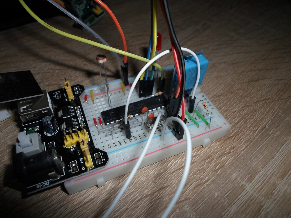
Now we need to attach our sensors, so the pins referenced in the sketch match up with the pinout reference for the ATmega328p which I’ve included above. At this stage, I’ll just show you a photo of the finished circuit, and I’ll describe it beneath:
![Now this may look super-confusing, and while it can definitely be a bit fiddly, once you get the hang of it, it does all make sense. It’s probably easiest to start with the rf24 transmitter. Connect the GND and 3.3V pins to the - and + lines of the breadboard respectively. In my circuit I’ve used a breadboard power supply with separate 3.3V and 5V outputs, to ensure I don’t overpower my rf24 transmitter. The CE pin goes to the penultimate pin on the left side of the ATmega unit (7), while the CS pin connects to the lowest pin on the left-hand side (8). Then, the SCK pin needs go to pin 13 of the ATmega, MISO connect to pin 12, and MOSI is connected to pin 11. For the PIR sensor, we can connect GND and VCC pins to - and + on the 5V rails of the breadboard, while the data pin in the middle connects to pin 4 of the ATmega (6th down on the left hand side). The DHT involves connecting GND and VCC again (I chose the 3.3V rail on my circuit). The data pin connects to pin 2 on the ATmega (4th pin on the left-hand side), and also to 3.3V rail via a 10k resistor. The door sensor requires 1 lead into GND, and the other to pin 6 (3rd from bottom on the left-hand side). The LDR photo-resistor requires 1 leg connected to 5V. The other leg connects to A0 (6th pin on the right-hand side), and also to GND via a 10k resistor. You should now be able plug it all in to mains, and be able to see your sensor readings reflected in OpenHab!]
Now this may look super-confusing, and while it can definitely be a bit fiddly, once you get the hang of it, it does all make sense.
It’s probably easiest to start with the rf24 transmitter. Connect the GND and 3.3V pins to the - and + lines of the breadboard respectively. In my circuit I’ve used a breadboard power supply with separate 3.3V and 5V outputs, to ensure I don’t overpower my rf24 transmitter.
The CE pin goes to the penultimate pin on the left side of the ATmega unit (7), while the CS pin connects to the lowest pin on the left-hand side (8).
Then, the SCK pin needs go to pin 13 of the ATmega, MISO connect to pin 12, and MOSI is connected to pin 11.
For the PIR sensor, we can connect GND and VCC pins to - and + on the 5V rails of the breadboard, while the data pin in the middle connects to pin 4 of the ATmega (6th down on the left hand side).
The DHT involves connecting GND and VCC again (I chose the 3.3V rail on my circuit). The data pin connects to pin 2 on the ATmega (4th pin on the left-hand side), and also to 3.3V rail via a 10k resistor.
The door sensor requires 1 lead into GND, and the other to pin 6 (3rd from bottom on the left-hand side).
The LDR photo-resistor requires 1 leg connected to 5V. The other leg connects to A0 (6th pin on the right-hand side), and also to GND via a 10k resistor.
You should now be able plug it all in to mains, and be able to see your sensor readings reflected in OpenHab!
Updated Parts List
DHT11: £1.10 each
Photoresistor: £0.20 each
PIR Sensor: £1.15 each
Reed Switch: £1.30 each
Breadboard: £0.30 each
ATmega328p: Approx. £1.60 each
rf24 Module: Approx. £1 each
Breadboard power supply Approx. £0.50 each
Total: Roughly £7, plus a few pence for jumper cables and resistors and so on.